Table of Contents
Managing Your INSTEON Network in Indigo
Indigo provides a variety of tools for managing your INSTEON network - not only can you add/control/delete devices, but you can also manage INSTEON Links so that you don't need to walk around your house pressing buttons (see the Managing INSTEON Links section for details). You can also replace devices and even your PowerLinc controller and Indigo will make sure that all links are modified so your network continues to work with as little manual intervention as possible. The first thing you should do, of course, is connect and configure your INSTEON interface.
INSTEON is primarily a power line technology, and as such is susceptible to signal noise. Check out the signal troubleshooting page for common causes and solutions to signal issues.
Connecting Insteon and X10 Power Line Interfaces
Connecting an Insteon (or X10 power line) interface to Indigo requires a couple of steps, described below. Check out our supported interfaces list to see if the interface you want to use has been tested with Indigo.
Install the FTDI VCP Drivers
The PowerLinc 2412U, 2413U, and 2448A7H (Insteon RF USB Adaptor) interfaces should be plugged directly into one of your Mac's USB ports (preferably not into a USB hub port) and require the FTDI Virtual COM Port (VCP) driver to be installed. If you are using Mac OS X 10.9 (Mavericks) or better, it has the driver already installed.
For earlier versions of the OS, you can get the driver installer at FTDI's web site - be sure to get the installer that's appropriate for the architecture of your machine (Intel or PowerPC). If you select PowerLinc 2412U/2412S/2413U/2413S/2448 from the Interface type popup menu in the Preferences dialog (see below), then Indigo will alert you if the driver is not installed on your Mac. If you're using a PowerLinc 2412S/2413S with a separate USB to serial adapter, you can ignore that warning alert. Note: there are known issues with the FTDI driver and macOS High Sierra, Mojave, and Catalina on some Macs - check out our blog post for details.
The PowerLinc 2414U/1132CU/1132U (all of which have now been discontinued) and CM15A (aka CM15Pro) interfaces should also be plugged directly into your computer (preferably not into a USB hub port) - the Indigo installer automatically installed the drivers for these interfaces. Make sure you have restarted after the installation process. If you reinstall your OS, then you will need to rerun the Indigo installer for the driver.
The other supported interfaces (PowerLinc 2412S/2413S, CM11 / HD11, LynX-PLC) are serial based, and will require a USB serial port adapter. If you are using one of the serial based interfaces, then make sure that the latest drivers for the USB serial adapter are installed on your system. Look on the adapter manufacturer's website for the latest driver downloads. If you don't already have a serial-to-USB adaptor, we highly recommend getting one that uses the same FTDI chipset that the PowerLincs use since it seems to be the most reliable.
Note: PowerLincs are quite sensitive to USB versions and hubs. It's known that there are often times failures on hubs (as mentioned above), but we also know that there are also failures on USB3 ports. In this last case, you may need to find a USB2 hub and use that for the PowerLinc.
Check the Interface Hardware list to see what interfaces we've actually tested.
Connecting the Interface
Plug the interface directly into an outlet (with the exception of the Insteon RF USB Adaptor). Do not plug the interface into your computer's power strip because many power strips contain filters that will severely degrade the INSTEON / X10 signal quality being received and transmitted by the interface. Additionally, uninterruptible power supplies (UPSs) can cause signal quality problems. If at all possible plug the interface into a different outlet than used by power strips and UPSs. Signal filters are available to isolate computer power strips and UPSs as well.
If you are using the CM11 / HD11 or CM15A interface, then do not install the battery into the interface. Indigo does not support uploading macros to these interfaces so the battery should not be used.
Configuring Indigo to use Your Interface
- Choose
Indigo 7→Preferences…menu, then make sure theInterfacestab is selected. - Select the
Enabledcheckbox next to theINSTEON / X10 Powerline Interfaceitem. - Double-click the
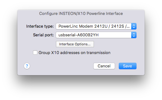
INSTEON/X10 Power Line Interfaceline in the table (you can also get to this dialog by selecting theInterfaces→INSTEON/X10 Power Line→Configure…menu item) - Choose your
Interface typein the popup menu.- If you are using the PowerLinc 2412U/2413U/2448A7H interface, then the
Serial port:popup menu will be enabled and the FTDI driver (see Install the Correct Drivers above) will create a newSerial port:popup menu item that looks likeusbserial-XXXXXXXX. Select that item. NOTE: you must have the FTDI driver installed already. - If you are using the PowerLinc 2414U/1132CU/1132U or the CM15 interface, then the
Serial port:popup menu will be disabled because these interfaces do not use a virtual serial port driver. - If you are using one of the serial based interfaces (PowerLinc 2412S, CM11 / HD11, LynX-PLC), then the
Serial port:popup menu will be enabled and you should choose which serial port adapter name the interface is connected to in theSerial port:popup menu. NOTE: if no names are listed in theSerial port:popup menu, then you probably do not have the proper driver installed for your USB serial adapter. Download your adapter's driver from the driver manufacturer's website.
- Optionally select the
Group addresses on transmissioncheckbox to combine like-command transmissions together. For example A1-On, A3-On, A4-On, would be transmitted as A1, A3, A4, On. - Some interfaces, such as the PowerLinc V2 and LynX-PLC, have additional settings that can be accessed from the Interface Options… button. Generally, these options don't need to be changed unless you're troubleshooting a problem.
Enabling and Disabling Communication
Choose the Interfaces→INSTEON/X10 Power Line→Disable (or Enable) menu item to disable/enable the interface.
Adding and Managing INSTEON Devices
Indigo uses Smart Link Syncing to quickly define and link INSTEON devices with the PowerLinc. This link syncing process will allow Indigo to control and see messages from the device.
First, make sure that Indigo has enabled communication with the interface. If Indigo is not online with the interface, then choose the Interfaces→INSTEON/X10 Power Line→Enable menu item. See connecting the Interface above for more details.
Additionally, make sure you have Insteon range extenders or other dual-band modules correctly installed on opposite power legs. If the range extenders or other dual-band devices are improperly installed or missing, then you may not be able to control some of your Insteon devices. See the instructions included with your Access Point RF pair for installation details.
TIP: Access Point RFs do not bridge X10 signals, so if you also have X10 devices you will likely need an additional bridge.
To add a new Insteon device:
- Select Devices in the Outline View of the Home window.
- Press the
New…button at the top of the Home window.
Here's the INSTEON device dialog:
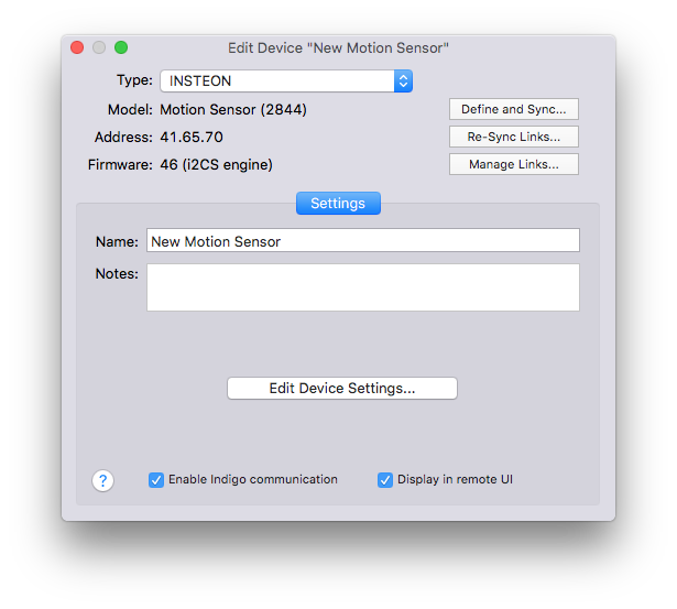
The Define and Sync… button will open the Define INSTEON Define dialog:
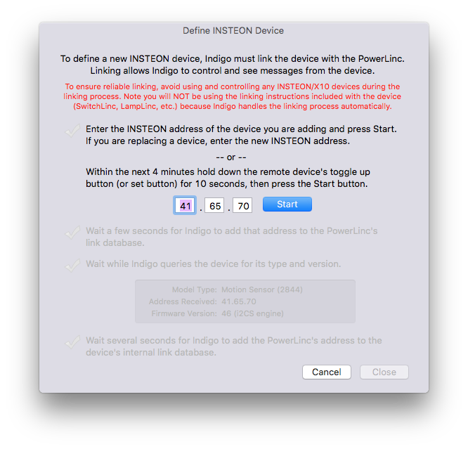
This is how you initially add an INSTEON device to Indigo. The directions on this dialog are quite self-explanatory. When you click the Start button you'll see the checkboxes turn green when each step is complete, and the Close button will enable when the process is complete. The sync process can take a few minutes to complete. Lamp and appliance devices normally take less than a minute, but KeypadLincs and ControLincs can take a few minutes because of the additional link information needed for all of the buttons.
If the sync process fails or does not complete, then make sure that the device is correctly wired or plugged in, both Access Point RFs are installed and on opposite power legs, and that you do not have an uninterruptible power supply (UPS) or surge protector strip plugged into the outlet the PowerLinc is using. If syncing still fails and the device is portable (ApplianceLinc or LampLinc), then try plugging it directly into the pass through outlet on the PowerLinc. See our signal troubleshooting tips for additional help.
After the sync dialog is closed, some devices, such as the KeypadLinc, EZRain, Thermostat Adapter, Motion Sensor, and EZIO8SA, have additional custom settings shown in the main device dialog.
Replacing and Resyncing Devices
The Re-Sync Links… button on the device edit dialog will open the Synchronize INSTEON Device Links dialog:
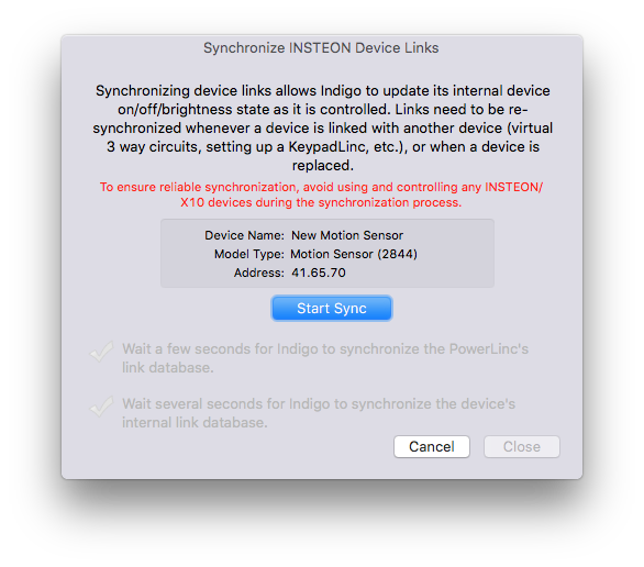
Use this dialog to resync a device when it's links have been altered outside of Indigo. You may be asked to use this dialog by technical support when troubleshooting device problems.
To replace a device that's malfunctioned, just open the edit dialog for the device and click the Define and Sync… button again to open the Define INSTEON Device dialog. Enter the address of the replacement module (and make sure it has been installed) and click the Start button just like you did when you originally added the device. This will maintain all the links that you created to and from the device as well as maintain any Triggers, Schedules, Conditions, Actions, and Control Pages that might use the device.
Managing INSTEON Links
The last button, Manage Links… is how Indigo allows you to remotely manage INSTEON links without having to walk around pressing set buttons (there is also a menu item on the INSTEON/X10 Power Line submenu to access the dialog).
The INSTEON protocol has linking built-in as part of it's core functionality. The idea is that one device, a controller in INSTEON speak, can be linked to another device, a responder, then from that point forward the controller device sends it's command directly to the responder device. So, for instance, you can link a KeypadLinc button to a SwitchLinc so that when you press the button on the KPL the SwitchLinc responds. That's normally done by pressing various buttons on each device in specific ways until the link is established.
The manual linking method is useful if you don't have a software-controlled environment. However, since you've decided to have Indigo automate your home, you do have software to help you manage your automation needs. We've worked very hard to allow Indigo to perform the majority of link management tasks remotely so you don't have to walk around pressing buttons.
For some background on INSTEON links, we have put together a separate page that discusses INSTEON Scenes. We highly recommend that you read through that page as it will give you a better understanding of what links are and how they work.
Managing INSTEON Device Links
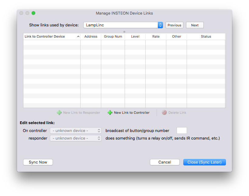
The primary place that you'll manage links between devices is in the Manage INSTEON Device Links dialog. Select the Interfaces→INSTEON/X10 Power Line→Manage Device Links menu item and the dialog will popup:
The dialog may look slightly different depending on the roles that the device selected in the popup at the top can play. As we mentioned earlier, devices that can control other devices are called “controllers” and devices that can be controlled are called “responders”. Many devices are both controllers and responders (the example above is a SwitchLinc, which is both). These links are also called groups and/or scenes, depending on usage, so keep that in mind.
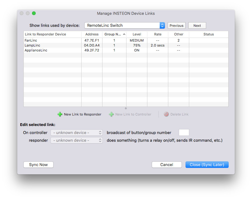
For example, you can use Indigo to remotely program the button on a RemoteLinc to: set a ceiling fan (FanLinc) to Medium, brighten a dimmer to 75% over 2 seconds, turn off an on/off device.
Indigo automatically creates the links to define the scene in most remote modules. This means you do not have to press-and-hold the set button or up paddle on most remote modules. Indigo will do it all remotely for you with a single press of the Sync Now button.
You can also define Indigo initiated scenes to control multiple remote modules in unison. See the defining INSTEON scenes section for more information on this capability.
Responder Modules vs. Controller Modules
Every INSTEON module is either a responder module, a controller module or both:
- Responder modules respond to incoming INSTEON commands by controlling a load (light or appliance), a thermostat setting, sprinkler valves, low-voltage relays, etc. Examples of responder modules include: LampLinc, ApplianceLinc, and the EZRain sprinkler controller.
- Controller modules send outgoing INSTEON commands onto the power line or via RF to modules that are responders. Examples of controller modules include: RemoteLinc, ControLinc, and the PowerLinc computer interface.
- Some modules are both responders and controllers. For example, a KeypadLinc can respond to a RemoteLinc but it can also control other modules, such as a LampLinc.
Defining the Scene between Modules
First, select the module you want to edit. You can choose to edit either the controller module in the scene (ex: RemoteLinc) or the responder module in the scene (ex: LampLinc).
- Select the
Interfaces→INSTEON/X10 Power Line→Manage Device Linksmenu item. - Select the module's device name to edit in the
Show links used by devicepopup control.
If the module you selected is a controller (RemoteLinc, KeypadLinc, SwitchLinc, etc.), then you can add or edit responders:
- If you want to add a new responder module to the scene, then press the
New Link to Responderbutton. If you want to change the settings (brightness, ramp rate duration, etc.) of an existing responder module in the scene, then select that module's link in the table with theLink to Responder Devicecolumn title. - Choose the button or group number that identifies the scene you are defining in the controller (ex: RemoteLinc button #1) from the
broadcast of button/group numberpopup control. - Choose the responder module's device name from the responder popup control (ex: LampLinc).
- When responding to a scene command, most modules will control the main load (light or appliance) connected to that module. For these modules (SwitchLinc, ToggleLinc, LampLinc, etc.) you can specify the exact brightness you want for that module as well as a duration for how quickly the module should go to that brightness: Some modules will have different options. For example, when a KeypadLinc is responding to a scene command, it can turn one of the secondary button LEDs on instead of controlling the main load, or the thermostat module can respond to a scene command by changing both the thermostat operation mode and the current
coolandheatsetpoint temperatures. - Optionally turn on the
Persistentcheckbox to force this link to automatically be restored whenever either the responder module or controller module is synced. If the modules are ever reset, replaced, or have this link modified, then Indigo will automatically rewrite the original link on the next sync operation. - Repeat steps 1 through 5 for every new responder module that you want to add to the selected controller.
If the module you selected is a responder (LampLinc, Thermostat Adapter, KeypadLinc, SwitchLinc, etc.), then you can add or edit controllers:
- If you want to add a controller of the selected responder module, then press the
New Link to Controllerbutton. If you want to change the settings (brightness, ramp rate duration, etc.) used by the selected module in a controller's scene, then select the controller module's link in the table with theLink to Controller Devicecolumn title. - Choose the controller module's device name from the On controller popup control (ex: RemoteLinc).
- Choose the button or group number that identifies the controller scene for which you want the responder to listen (ex: RemoteLinc button #3) from the
broadcast of button/group numberpopup control. - When responding to a scene command, most modules will control the main load (light or appliance) connected to that module. For these modules (SwitchLinc, ToggleLinc, LampLinc, etc.) you can specify the exact brightness you want for that module as well as a duration for how quickly the module should go to that brightness using the % text box and the rate popup. Some modules will have different options. For example, when a KeypadLinc is responding to a scene command, it can turn one of the secondary button LEDs on instead of controlling the main load, or the thermostat module can respond to a scene command by changing both the thermostat operation mode via the mode popup and the current
coolandheatsetpoint temperatures via those text boxes. - Optionally turn on the
Persistentcheckbox to force this link to automatically be restored whenever either the responder module or controller module is synced. If the modules are ever reset, replaced, or have this link modified, then Indigo will automatically rewrite the original link on the next sync operation. - Repeat steps 1 through 5 for every new controller module you want to add for the selected responder.
Lastly, to have Indigo write all of your link changes to the remote modules, press the Sync Now button to have Indigo immediately write all changed links to the remote modules. Or, press the Close (Sync Later) button to close the link editor window and write the changes to the modules at a later time. When you are ready to write the changes to the remote modules, select Start Sync Device Links… from the Interfaces→INSTEON/X10 Power Line menu, and then press the press the Sync Changes Only button.
Manually Creating Links between Modules
In addition to using Indigo's remote link and scene management, you can also manually create the links physically at the devices themselves. Follow the instructions that came with the hardware for the exact steps, which usually involves creating the links by press-and-holding the set button or up paddles for 10 seconds on each module.
If you manually create or delete a link, then you must tell Indigo to re-sync those modules. This enables Indigo to read in the link changes, and is required for Indigo to accurately show the state of the modules as they change.
Managing INSTEON PowerLinc Scenes
INSTEON scenes (also called groups) can be used to control multiple INSTEON modules, such as light switch modules, lamp or appliance plug-in modules, and thermostat modules, all in unison. For example, you could create a home theatre lighting scene that turns off all lighting in your media room, except for a few sconce side lights which are set to 20% brightness. You can create lighting scenes for any activity you desire: dining, entertaining, sleeping, reading in bed, emergency, etc.
Indigo can remotely create scenes in the computer interface (PowerLinc) that control multiple remote modules. Indigo automatically creates the links to define the scene in both the PowerLinc and most remote modules. This means you do not have to press-and-hold the button on either the PowerLinc or most remote modules. Indigo will do it all remotely for you with a single press of the Sync Now button.
Once Indigo writes the links defining the scene to the PowerLinc and remote modules, you can execute the scene from any Trigger, Schedule, or Action Group using the Execute INSTEON Scene action.
Indigo can also remotely create and edit scenes between remote modules (ex: from a KeypadLinc to a LampLinc). See Managing INSTEON Device Links for more information on this capability.
Defining the Scene
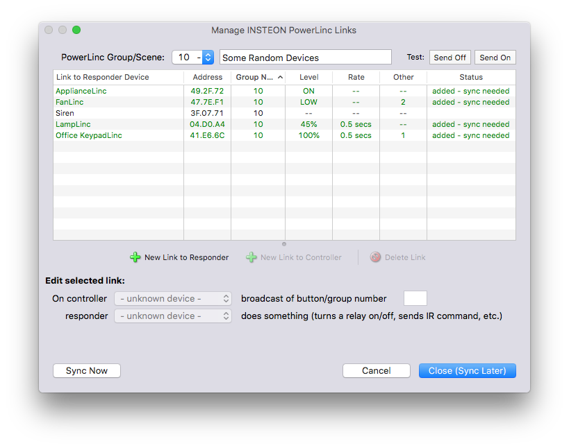
First, specify which PowerLinc Group/Scene number you want to use:
- Choose
Manage PowerLinc Links…from theInterfaces→INSTEON/X10 Power Linemenu. - Select a
PowerLinc Group/Scenenumber to use for the scene. Use 1 if this is your first scene. - Optionally enter a
PowerLinc Group/Scenename in the edit field (ex: “reading in bed”).
Next, create a new link for every responder module in the scene:
- If you want to add a new responder module to the scene, then press the
New Link to Responderbutton. If you want to change the settings (brightness, ramp rate duration, etc.) of an existing responder module in the scene, then select that module's link in the table in the top-half of the window. - Choose the responder module's device name from the
responderpopup control. - When responding to a scene command most modules will control the main load (light or appliance) connected to that module. For these modules (SwitchLinc, ToggleLinc, LampLinc, etc.) you can specify the exact brightness you want for that module as well as a duration for how quickly the module should go to that brightness by using the % text box and the duration popup. Some modules will have different options. For example, when a KeypadLinc is responding to a scene command it can turn one of the secondary button LEDs on instead of controlling the main load, or the thermostat module can respond to a scene command by changing both the thermostat operation mode via the mode popup and the current
coolandheatsetpoint temperatures using the text boxes. - Optionally turn on the
Persistentcheckbox to force this link to automatically be restored whenever the responder module is synced. If the responder module is ever reset, replaced, or has this link modified, then Indigo will automatically rewrite the original link into the device when it is next synced. - Repeat steps 1 through 4 for every new module you want to add to the scene.
Lastly, have Indigo write all of your link changes to both the PowerLinc and the remote modules by pressing the Sync Now button to have Indigo immediately write all changed links to the PowerLinc and remote modules. Or, press the Close (Sync Later) button to close the link editor window and write the changes to the modules at a later time. When you are ready to write the changes to the PowerLinc and remote modules select Start Sync Device Links… from the Interfaces→INSTEON/X10 Power Line menu, and then press the press the Sync Changes Only button.
You can test the scene after the links are written by using the Send On and Send Off buttons.
Executing the Scene
The Indigo scene can now be executed from any Trigger, Schedule, or Action Group:
- Select the
Actionstab inside the edit window. - Select
INSTEON Actions→Execute INSTEON Scenefrom the actionTypepopup item. - Use the
Sendpopup item to select which scene command to send:Group Onwill command all of the responder modules to their scene-specific brightness using their scene-specific ramp rate duration, if any.Group On to 100% (instant / ignore rate)will set the brightness of dimmable modules to 100% immediately, ignoring any ramp rate duration.Group Offwill turn off all of the responder modules using their scene-specific ramp rate duration, if any.Group Off (instant / ignore rate)will turn off all of the modules immediately, ignoring any ramp rate duration.
- Select the scene number defined previously (see above) from the
Scenepopup item.
Note: you can press the Modify this Scene button… to add a new responder module to the currently selected scene, or you can double-click a device in the scene list to edit its settings (brightness, ramp rate duration, etc.).
INSTEON Link Syncing
Indigo's smart INSTEON Link Syncing makes it easy to setup and keep all of your devices working with your PowerLinc. This link syncing process allows Indigo to control devices, and to update its internal device state (on / off / brightness) as the device is controlled locally (at the switch) or remotely by other devices. Indigo shows the state of all INSTEON devices as they change, even if the change is because of a command from another device. For example, a LampLinc that is turned ON from a ControLinc will immediately show as ON within Indigo. Indigo automatically does link syncing when you first create the device.
If, after the device is initially created, a remote device has any additional controller links added (ex: LampLinc is controlled by a KeypadLinc), then that device (LampLinc in this case) should have its links re-synced. This option is available from the Device dialog and will ensure Indigo has an accurate representation of the device's internal links, allowing it to correctly show state (on / off / brightness) changes as they occur.
Re-Syncing a Single INSTEON Device
Make sure the device is properly wired or plugged in. Select Device List from the View menu. Double-click the device you need to re-sync. Press the Re-Sync Links… button. Press the Start Synch button. Wait for the Smart Link Syncing steps to complete and press the Close button. The sync process can take a few minutes to complete. Lamp and appliance devices normally take less than a minute, but KeypadLincs and ControLincs can take a few minutes because of the additional link information needed for all of the buttons.
Re-Syncing All INSTEON Devices
In addition to syncing individual devices, you can also batch sync all of your INSTEON devices. Depending on the number of INSTEON devices you have, this process can take a significant amount of time to complete. Because control of your devices will be limited during the synchronization process, it is recommended that you start the synchronization process at night or before you leave the house.
Make sure all devices are properly wired or plugged in. Select Start Sync Device Links… from the Interface menu. Press the Sync All Devices button. Watch the Event Log window to see when the synchronization process is complete. The batch synchronization process can be canceled at any time.
Select Stop Sync Device Links from the Interface menu. Watch the Event Log window to see when the synchronization process is canceled.
Resetting your PowerLinc
Sometimes, customer support will ask you to reset your PowerLinc. Here's the process:
- In Indigo 5 or above, select the
Interfaces→Insteon/X10 Power Line→Disablemenu item - Unplug your PowerLinc and wait about 15 seconds
- Press and hold the black set button on the side
- While holding the button, plug it back in and continue to hold the button for about 15 seconds
- Release the button
- In Indigo, select the
Interfaces→Insteon/X10 Power Line→Enablemenu item - Select the
Interfaces→Insteon/X10 Power Line→Configure…menu item - Click the
Interface Options…button - Click the
Sync Linksbutton
The last step will take a while, so watch the Event Log window for progress.
Replacing Your PowerLinc
If your PowerLinc is ever replaced, then you must re-sync all of your devices. This will ensure that all devices have their internal links updated to reflect the new PowerLinc's INSTEON address. If you are replacing a 2414U with a newer PowerLinc, you may also need to install the drivers for your new PowerLinc.
Once you have the driver installed, just connect the PowerLinc to your Mac. If you're switching from a 2414 to one of the current ones, you'll need to select it in the config dialog for INSTEON. Otherwise you'll need to select the new Serial Port in that same dialog. Once you click “Save” on that dialog, Indigo will prompt you to resync all links - do that. Once it's done, all links in all devices should be correct. Be sure to have any battery-powered devices close at hand - you'll need to press and hold the set button to wake them up.
Note: that any links that you create, either using the UIs described above, or by manual linking must be marked as Persistent in the link dialogs in order for them to be recreated correctly. For links that you create manually between devices, when you have the manual links created successfully, you must come back to Indigo and sync the device(s) links. The manual links will show up in the dialogs - you must then mark them as Persistent in order for them to be retained when doing a resync/replacement.
Other INSTEON Features in Indigo
The Interfaces→INSTEON/X10 Power Line submenu contains a collection of miscellaneous INSTEON commands that will help you manage specific aspects of devices as well as do so low-level INSTEON commands not directly supported in the UI:
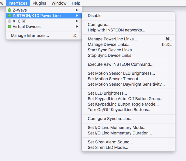
Note that these are also actions available in the Insteon Brand Specific submenu.
Execute Raw INSTEON Command
This action will allow you to send a raw INSTEON command to any INSTEON device. You can send standard messages (2 bytes) or extended messages (16 bytes). You can also have the results of the command inserted into a variable for later processing.
Set Motion Sensor LED Brightness
This action will set the brightness of the LED that flashes inside the motion sensor when motion is detected. While the brightness value is between 0 and 255, 0 does not mean the LED is completely off - it's just very dim. Note: only revision 2 Motion Sensors with jumper 5 set can be configured.
Set Motion Sensor Timeout
This action will set the timeout value between the time the motion sensor stops detecting motion and when it sends the OFF command. The timeout values work like this: 0 is equal to 30 seconds and 255 is equal to 2 hours. Values in between are proportional to those values.
Note: only revision 2 Motion Sensors with jumper 5 set can be configured.
Note: a value of 0 will be interpreted as 3 for Motion Sensor II models.
Set Motion Sensor Day/Night Sensitivity
This action will set the sensitivity for when the motion sensor detects changes from dawn to dusk and vice versa. The sensitivity values work like this: 0 will make the sensor register day all the time and 255 is equal to night all the time. Values in between are proportional to those values. Note: only revision 2 Motion Sensors with jumper 5 set can be configured.
Set LED Brightness
This action will set the brightness of the LEDs on certain devices. Newer KeypadLincs are supported as well as some SwitchLinc models. Unfortunately there isn't really a way to tell you which devices are supported so you'll just have to try it and see if it works.
You can script this action from Python:
insteonId = "com.perceptiveautomation.indigoplugin.InsteonCommands"
insteonPlugin = indigo.server.getPlugin(insteonId)
if insteonPlugin.isEnabled():
    actionProps = dict()
    actionProps["brightness"] = 1  # a value from 1-100
    actionProps["device"] = 123456  # the ID of the KeypadLinc or SwitchLinc
    actionProps["brightenMethod"] = "kpl"  # the device is a KeypadLinc - use "swl" if it's a SwitchLinc
    insteonPlugin.executeAction("setLedBrightness", props=actionProps)
Set KeypadLinc Auto-Off Button Group
This action will allow you to specify what buttons will go off automatically when you press any other button. Useful in conjunction with Toggle Mode below for creating “radio groups”. See the FanLinc and KeypadLinc article for usage examples.
Set KeypadLinc Button Toggle Mode
This action will allow you to specify whether a button toggles (alternates between ON and OFF when pressed) or whether it sends a single command anytime it's pressed (can send either ON or OFF). Useful in conjunction with Auto-Off groups above for creating “radio groups”. See the FanLinc and KeypadLinc article for usage examples.
Turn On/Off KeypadLinc Buttons
This action allows you to turn on/off groups of buttons. Why not just have multiple actions using the built-in Turn ON/Turn OFF LED actions? Because each of those requires a lot of INSTEON traffic - and if you need to set several buttons at once this action will do it in one (or two if you want to maintain some buttons) action(s). It's more efficient and easier to configure (one action versus potentially seven actions). Select the action you want to take for each button: Turn On, Turn Off, Leave Alone. The latter option will require that we query the KPL to find the states first so if you select that for any of the buttons the action may execute a bit slower than it would otherwise.
Note: using this action, which is sending raw INSTEON commands through the IndigoServer, will cause the KeypadLinc's button states in Indigo to become out of sync. This is because the server doesn't know that you're changing the button states given that it's just a raw command message that it's being asked to send to the PowerLinc. If you need to keep the states in sync then add another action to do a status request to the KeypadLinc (after a short delay to avoid collisions).
Configure SynchroLinc
This action will allow you to configure the Trigger Watts, Threshold Watts, and Delay Seconds in a SynchroLinc. Here are the details of those settings:
- Trigger Watts (0 to 1800 watts in 0.5 watt steps): the wattage needed before the SynchroLinc broadcasts.
- Threshold Watts (aka hysteresis, 0 to 127.5 watts in 0.5 watt steps): tolerance before on/off toggle is sent.
- Delay Seconds (0.15 to 38.25 seconds): prevents message flooding if thresholdWatts is too low.
Set I/O Linc Momentary Mode
This action will allow you to set the momentary mode of an I/O Linc to A, B, C, or None (the built-in UI only sets A or None).
Set Siren Alarm Sound
This action will allow you to set the sound that the siren makes when it's turned on. The choices are chime which is a softer sound, and siren which is a very loud sound.
Set Siren LED Mode
This action will allow you to set how the LED on the siren behaves. The LED can always be on or off, or it can flicker based on Insteon traffic.
Set OutletLinc Load Sense
This action will allow you to turn the load sense feature of the dual outlet OutletLinc on and off (on either the top or bottom outlet).

